Table of contents:
- General information
- Analog passive filters
- Analog active filters
- IIR filters
- FIR filters
- Moving average filters
- Custom filters
General information
Because it's a list of filters, when first placing the symbol there will be a lot of listed parameters, which may be confusing, but no filter in particular will use every one of them. Some will be common, some won't, but unused parameters can be safely deleted or added anytime, there are builtin defaults for each.
Similarly, not all pins are used, or even needed but, no matter what type of filter, the most basic usage means using pins IN, OUT, and GROUND; the rest have various other uses. The GROUND pin must be used at all times!
Frequency graphs
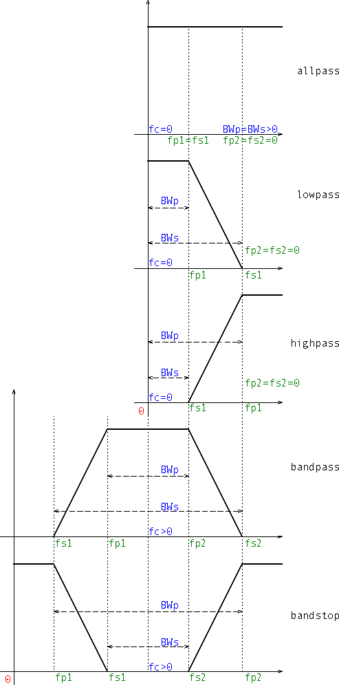
- Specify the corner frequencies through parameters fp1, fs1, fp2, and fs2. This is similarly to the way the frequency vectors are specified in Octave, and the default settings (green values in the graph below).
- allpass: 0 < fp1 = fs1, fp2 = fs2 = 0
- lowpass: fp1 < fs1, fp2 = fs2 = 0
- highpass: fs1 < fp1, fp2 = fs2 = 0
- bandpass: fs1 < fp1 < fp2 < fs2
- bandstop: fp1 < fs1 < fs2 < fp2
- Specify the bandwidths and central frequency through BWp, BWs, and fc. Set these by first deleting the previous four (blue values in the graph below).
- allpass: 0 < BWp = BWs, fc = 0
- lowpass: BWp < BWs, fc = 0
- highpass: BWs < BWp, fc = 0
- bandpass: BWp < BWs, fc > 0
- bandstop: BWs < BWp, fc > 0
Basic usage
- Specify the passband and stopband frequencies and attenuations, and set the order to zero, which triggers its automatic calculation internally (f0 is for digital filters only):
- sigma nT Zin Zout
- Win Choice sim SH Norm
- (f0) fp1 fs1 fp2 fs2
- G Asc Ap As N=0
- Specify the order and the passband frequencies and attenuations, which results in the stopband frequencies and attenuations to be automatically determined based on whether they are less or greater than their passband counterparts, according to the graphs above:
- sigma nT Zin Zout
- Win Choice sim SH Norm
- (f0) fp1 fs1 fp2 fs2
- G Asc Ap As N>0
The same is valid for the alternate way of setting the frequencies.
Analog passive filters
There are two filters available: Butterworth and Chebyshev (type I). They are LC ladders built in Cauer's form, singly- or doubly-terminated ports, and they can form lowpass, highpass, bandpass, or bandstop configurations. Trying to configure them as allpass (fp1=fs1>0, fp2=fs2=0) will result in "undefined behaviour". Whether they start with an inductance or a capacitance, or with a series or shunt element, it's established based on user input (internally autoconfigured), as shown below:
| ( Zin≤Zout & Zin>0 ) ^ Zin==-1 ^ Zout==0 |
( Zin>Zout & Zout>0 ) ^ Zin==0 |
 |
 |
The internal numbering of the elements doesn't consider the type of the element, L or C, only its position in the ladder.
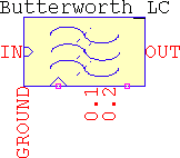
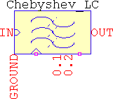
Both filters use the same pins:
-
Pin 0.1 outputs the order: in
.TRANit's in V, and in.ACit's in dB and deg. Zero resistance output. -
Pin 0.2 outputs the normalized values of the elements of the lowpass prototype, but only in
.TRAN. For example, if the filter is a 6th order bandpass with equal terminating impedances (non-null), the lowpass prototype will be a Π CLC filter, and if the simulation card is.TRAN 30m, then by setting sim=30m, the output will be a staircase-like voltage having three values: the first for the input shunt capacitor, the second for the series inductor, and the third for the terminating shunt capacitor.
Butterworth_LC
| Zin=<-1,0,0+..∞> | Ω | Input impedance. There are three possible settings:
|
| Zout=<0,0+..∞> | Ω | Output impedance. There are two possible settings:
|
| Only one of the impedances can be zero at a time! | ||
| fp1, fs1, fp2, fs2 | Hz | Corner frequencies for the passband and stopband, defaults <500,400,2k,2.5k> |
| BWp, BWs, fc | Hz | Alternate frequency settings: passband bandwidth, stopband bandwidth, and center frequency, defaults are calculated based on the corner frequencies and, based on those, <1.5k,2.1k,1k> |
| As | dB | Stopband attenuation, default 40 |
| Asc | dB | Frequency-scaling attenuation. If Asc=0, N>0 the passband is optimized. Default 3.0103 |
| N=<0:1:32> N=<0:2:64> |
- | Order of the filter, its value represents the order after the frequency transformations. For lowpass and highpass the maximum order is 32 and can take odd and even values. For bandpass and bandstop it's 64, but only even values are valid. If N=0 and Asc>0, the minimum order is determined based on the values of the frequencies and attenuations. Default 13 |
| sim | s | Total .TRAN simulation time, default 1 |
| Rpar, Rser | Ω | LTspice's specific for inductors and capacitors, common for both (i.e. setting Rser means inductors and capacitors, together, will have it set, same for Rpar), defaults <1g,0> |
Chebyshev_LC
| Zin=<-1,0,0+..∞> | Ω | Input impedance. There are three possible settings:
|
| Zout=<0,0+..∞> | Ω | Output impedance. There are two possible settings:
|
| Only one of the impedances can be zero at a time! | ||
| fp1, fs1, fp2, fs2 | Hz | Corner frequencies for the passband and stopband, defaults <500,400,2k,2.5k> |
| BWp, BWs, fc | Hz | Alternate frequency settings: passband bandwidth, stopband bandwidth, and center frequency, defaults are calculated based on the corner frequencies and, based on those, <1.5k,2.1k,1k> |
| Ap | dB | Passband ripple. If Ap=0, N>0 the passband is optimized. Default 1 |
| As | dB | Stopband attenuation. If As=0, N>0 the stopband is optimized. This is the same as As>0, N=0. Default 40 |
| Asc | dB | Frequency-scaling attenuation. If Asc≤Ap, Ap will be considered. Default 3.0103 |
| N=<0:1:32> N=<0:2:64> |
- | Order of the filter, its value represents the order after the frequency transformations. For lowpass and highpass the maximum order is 32 and can take odd and even values. For bandpass and bandstop it's 64, but only even values are valid. If N=0 and Ap>0 or As>0, the minimum order is determined based on the values of the frequencies and attenuations. Default 13 |
| sim | s | Total .TRAN simulation time, default 1 |
| Rpar, Rser | Ω | LTspice's specific for inductors and capacitors, common for both (i.e. setting Rser means inductors and capacitors, together, will have it set, same for Rpar), defaults <1g,0> |
Examples
- Doubly-terminated port
- Lowpass
- Highpass
- Bandpass
- Bandstop
- Singly-terminated port
- High impedance (current source) input
- Zero impedance (voltage source) input
- Zero impedance (shorted) output
- The test pins
Doubly-terminated port
- Lowpass: minimum order Butterworth for a -3dB@1rad, -60dB@2rad for unity source/load. sim is not used, so it's grayed out. Note that the attenuations are relative to the DC gain.
- Butterworth_LC
- sigma nT Zin=1 Zout=1
- Win Choice sim SH Norm
- f0 fp1={2*pi} fs1={4*pi} fp2=0 fs2=0
- G Asc=3 Ap As=60 N=0
- Highpass: minimum order Chebyshev for a -3dB@100MHz, 1dB ripple, -50dB@50Mhz, 50Ω to 75Ω adaptor. The resulting order is even (6) and the output resistance is lower than the minimum allowed value of Zin/tanh(asinh(1/εp)/2)2≈133Ω, so the output is distorted (intentional).
- Chebyshev_LC
- sigma nT Zin=50 Zout=75
- Win Choice sim SH Norm
- f0 fp1=100meg fs1=50meg fp2=0 fs2=0
- G Asc=3 Ap=1 As=50 N=0
- Bandpass: minimum order Butterworth, -3dB@[100Hz, 10kHz], -60dB@[50Hz, 20kHz], Zin=Zout=8Ω.
- Butterworth_LC
- sigma nT Zin=8 Zout=8
- Win Choice sim SH Norm
- f0 fp1=100 fs1=50 fp2=10k fs2=20k
- G Asc=3 Ap As=60 N=0
- Bandstop: minimum order Chebyshev, 1kHz central frequency, 0.1dB@1kHz passband bandwidth, -80dB@2kHz stopband bandwidth, 0.1dB ripple (Asc≤Ap ⇒ no frequency scaling), Zin=Zout=600Ω. In this case it's easier to work with the alternate way of entering frequencies. The resulting order, as shown at pin 0.1, is 18, thus the lowpass prototype would be 18/2=9, odd order means the load has no restrictions.
- Chebyshev_LC
- sigma nT Zin=600 Zout=600
- Win Choice sim SH Norm
- f0 fc=1k BWp=1k BWs=2k
- G Asc=0 Ap=0.1 As=80 N=0
Singly-terminated port. A 4th order Butterworth lowpass prototype will be shown for all three cases.
- High impedance (current source) input:
- Butterworth_LC
- sigma nT Zin=0 Zout=1
- Win Choice sim SH Norm
- f0 fp1=1 fs1=2 fp2=0 fs2=0
- G Asc=3.0103 Ap As=0 N=4
- Zero impedance (voltage source) input:
- Butterworth_LC
- sigma nT Zin=-1 Zout=1
- Win Choice sim SH Norm
- f0 fp1=1 fs1=2 fp2=0 fs2=0
- G Asc=3.0103 Ap As=0 N=4
- Zero impedance (shorted) output:
- Butterworth_LC
- sigma nT Zin=1 Zout=0
- Win Choice sim SH Norm
- f0 fp1=1 fs1=2 fp2=0 fs2=0
- G Asc=3.0103 Ap As=0 N=4
The test pins
- Suppose the simulation card is
.TRAN 5and the filter is a Chebyshev type I with:- Chebyshev_LC
- sigma nT Zin=1 Zout=1
- Win Choice sim=5 SH Norm
- f0 fp1=1 fs1=2 fp2=20 fs2=10
- G Asc=0 Ap=0.1 As=40 N=0
This results in a 10th order bandstop, thus a 5th order lowpass prototype. Probing the voltage at pin 0.2 will reveal a staircase voltage with 5 steps: 1.146813, 1.3712126, 1.9750031, 1.3712126, 1.146813 (as read by the cursor). Since the impedances are equal, the first element is a series inductance thus, after the frequency transformations, it's a parallel LC.
Analog active filters
Bessel
-
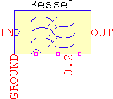
In
.TRAN, pin 0.2 outputs the normalized values of the underlying Bessel polynomial. For best readings, sim should be set to match the total simulation time. These values appear as the recursive formula, starting from the highest valued coefficient (a0), to the lowest:
 For example, a 4th order has the resulting polynomial s4+10s3+45s2+105s+105. The highest term is 105, and the next one is also 105, so the ratio is always 1 for the first term. Then, the second ratio will be 105/45=2.333, the 3rd will be 45/10=4.5, and the last 10/1=10. These are the values of the staircase voltage. Rebuilding the polynomial is done by recursively multiplying the terms: 1*10=10, 10*4.5=45, 45*2.333=105, 105*1=105.
- The frequency scaling is done via a polynomial fit, thanks to zunzun↗. For Asc=3.0103, the maximum difference between the highest and lowest trace for N=1 and N=32 is ~310mdB, while the difference between two adjacent traces is ~12.5mdB. The errors tend to be proportional to Asc.
- Even if unlikely, Bessel supports all five configurations: allpass, lowpass, highpass, bandpass, and bandstop.
| fp1, fs1, fp2, fs2 | Hz | Corner frequencies for the passband and stopband, defaults <500,400,2k,2.5k> |
| BWp, BWs, fc | Hz | Alternate frequency settings: passband bandwidth, stopband bandwidth, and center frequency, defaults are calculated based on the corner frequencies and, based on those, <1.5k,2.1k,1k> |
| Asc | dB | Frequency-scaling attenuation, absolute values only.
|
| N=<1:32> | - | Order of the filter. It represents the order of the lowpass prototype. For bandpass and bandstop, if N=5, it will actually be a 10th order. There is no automatic order calculation, therefore N must not be null. Default 13 |
| G | - | Gain, linear, default 1 |
| sim | s | Total .TRAN simulation time, default 1 |
| Rpar | Ω | LTspice's specific for inductors and capacitors, default 1g |
Butterworth
-
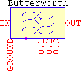
Pin 0.1 outputs the order: in
.TRANit's in V, and in.ACit's in dB and deg. Zero resistance output. -
In
.TRAN, pin 0.2 will output the real parts of the poles, and 0.3 the imaginary parts of the poles of the lowpass prototype. For best readings, sim should be set to match the total simulation time. For example, a 10th order bandpass results from a 5th order lowpass prototype, and has 3 roots: 2 complex conjugate, and one real. - It supports all five configurations: allpass, lowpass, highpass, bandpass, and bandstop.
| fp1, fs1, fp2, fs2 | Hz | Corner frequencies for the passband and stopband, defaults <500,400,2k,2.5k> |
| BWp, BWs, fc | Hz | Alternate frequency settings: passband bandwidth, stopband bandwidth, and center frequency, defaults are calculated based on the corner frequencies and, based on those, <1.5k,2.1k,1k> |
| As | dB | Stopband attenuation, absolute values only, default 40 |
| Asc | dB | Frequency-scaling attenuation, absolute values only. If Asc=0, N>0 the passband is optimized. Default 3.0103 |
| N=<0:32> | - | Order of the filter. It represents the order of the lowpass prototype. For bandpass and bandstop, if N=5, it will actually be a 10th order. If N=0, Asc>0, As>0, it determines the minimum order to meet specifications. Default 13 |
| G | - | Gain, linear, default 1 |
| sim | s | Total .TRAN simulation time, default 1 |
| Rpar | Ω | LTspice's specific for inductors and capacitors, default 1g |
Chebyshev
-
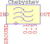
Pin 0.1 outputs the order: in
.TRANit's in V, and in.ACit's in dB and deg. Zero resistance output. -
In
.TRAN, pin 0.2 will output the real parts of the poles, and 0.3 the imaginary parts of the poles of the lowpass prototype. For best readings, sim should be set to match the total simulation time. For example, a 10th order bandpass results from a 5th order lowpass prototype, and has 3 roots: 2 complex conjugate, and one real. - It supports all five configurations: allpass, lowpass, highpass, bandpass, and bandstop.
| fp1, fs1, fp2, fs2 | Hz | Corner frequencies for the passband and stopband, defaults <500,400,2k,2.5k> |
| BWp, BWs, fc | Hz | Alternate frequency settings: passband bandwidth, stopband bandwidth, and center frequency, defaults are calculated based on the corner frequencies and, based on those, <1.5k,2.1k,1k> |
| Ap | dB | Passband ripple, absolute values only. If Ap=0, N>0 the passband is optimized. Default 1 |
| As | dB | Stopband attenuation, absolute values only, default 40 |
| Asc | dB | Frequency-scaling attenuation, absolute values only. If Asc≤Ap, Ap is considered. Default 3.0103 |
| N=<0:32> | - | Order of the filter. It represents the order of the lowpass prototype. For bandpass and bandstop, if N=5, it will actually be a 10th order. If N=0, Asc>0, Ap>0, As>0, it determines the minimum order to meet specifications. Default 13 |
| G | - | Gain, linear, default 1 |
| nT=<-1,0> | - | Tweak to mimic the response of a passive filter. Even order filters will have the gain at the corner frequencies:
|
| sim | s | Total .TRAN simulation time, default 1 |
| Rpar | Ω | LTspice's specific for inductors and capacitors, default 1g |
InvChebyshev
-
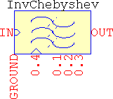
Pin 0.1 outputs the order: in
.TRANit's in V, and in.ACit's in dB and deg. Zero resistance output. -
In
.TRAN, pin 0.2 will output the real parts of the poles, 0.3 the imaginary parts of the poles, and 0.4 the imaginary parts of the zeroes of the lowpass prototype. For best readings, sim should be set to match the total simulation time. For example, a 10th order bandpass results from a 5th order lowpass prototype, and has 3 roots -- 2 complex conjugate, and one real --, and 2 zeroes -- the 3rd is null. - The supported configurations are: lowpass, highpass, bandpass, and bandstop.
| fp1, fs1, fp2, fs2 | Hz | Corner frequencies for the passband and stopband, defaults <500,400,2k,2.5k> |
| BWp, BWs, fc | Hz | Alternate frequency settings: passband bandwidth, stopband bandwidth, and center frequency, defaults are calculated based on the corner frequencies and, based on those, <1.5k,2.1k,1k> |
| As | dB | Stopband attenuation, absolute values only. If As=0, Asc>0, N>0 the transition band is optimized. Default 40 |
| Asc | dB | Frequency-scaling attenuation, absolute values only. If Asc=0, As>0, N>0 the passband is optimized. If Asc≥As, As is considered. Default 3.0103 |
| N=<0:32> | - | Order of the filter. It represents the order of the lowpass prototype. For bandpass and bandstop, if N=5, it will actually be a 10th order. If N=0, Asc>0, As>0, it determines the minimum order to meet specifications. Default 13 |
| G | - | Gain, linear, default 1 |
| sim | s | Total .TRAN simulation time, default 1 |
| Rpar | Ω | LTspice's specific for inductors and capacitors, default 1g |
Cauer
-
It uses approximations after Antoniou, further simplified and tweaked in order to accomodate LTspice. This means that the response will not be strictly ideal, but the errors are very small for practical applications (one or two decimals short of
float), but they do get noticeable for more extreme cases, such as high ripple + low stopband attenuation, or very small ripple + very large attenuations. In general, usage of Ap=<0.001..3> and As=<20..120> should not be problematic. - Related to the above, calculating filters using the first method (letting the order be automatically determined) is usually more accurate and more tolerant for extreme cases than imposing the order. This is due the way the eliptic nome q is calculated internally.
-
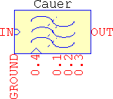
Pin 0.1 outputs the order: in
.TRANit's in V, and in.ACit's in dB and deg. Zero resistance output. -
In
.TRAN, pin 0.2 will output the real parts of the poles, 0.3 the imaginary parts of the poles, and 0.4 the imaginary parts of the zeroes of the lowpass prototype. For best readings, sim should be set to match the total simulation time. For example, a 10th order bandpass results from a 5th order lowpass prototype, and has 3 roots -- 2 complex conjugate, and one real --, and 2 zeroes -- the 3rd is null. - The supported configurations are: lowpass, highpass, bandpass, and bandstop.
| fp1, fs1, fp2, fs2 | Hz | Corner frequencies for the passband and stopband, defaults <500,400,2k,2.5k> |
| BWp, BWs, fc | Hz | Alternate frequency settings: passband bandwidth, stopband bandwidth, and center frequency, defaults are calculated based on the corner frequencies and, based on those, <1.5k,2.1k,1k> |
| Ap | dB | Passband ripple, absolute values only. If Ap=0, As>0, Asc>0, N>0 the passband is optimized. If Asc≥As, As is considered. Default 3.0103 |
| As | dB | Stopband attenuation, absolute values only. If As=0, Asc>0, N>0 the transition band is optimized. Default 40 |
| Asc | dB | Frequency-scaling attenuation, absolute values only. If Asc≥As, As is considered. If Asc≤Ap, Ap is considered. Default 3.0103 |
| N=<0:32> | - | Order of the filter. It represents the order of the lowpass prototype. For bandpass and bandstop, if N=5, it will actually be a 10th order. If N=0, Asc>0, Ap>0, As>0, it determines the minimum order to meet specifications and optimizes the transition band. Default 13 |
| G | - | Gain, linear, default 1 |
| nT=<-1,0> | - | Tweak to mimic the response of a passive filter. Even order filters will have the gain at the corner frequencies:
|
| sim | s | Total .TRAN simulation time, default 1 |
| Rpar | Ω | LTspice's specific for inductors and capacitors, default 1g |
Examples
- Allpass, Bessel, 1ms@1kHz. If it's allpass, the group delay is doubled, so fp=2/(2*π*τ)=318.3Hz. Asc=0 means classic group delay design and, as per the frequency graphs, fp1=fs1>0, fp2=fs2=0. In addition, the order needs to be at least 6 so that the group delay meets the specifications within an acceptable margin of error:
- Bessel
- sigma nT Zin Zout
- Win Choice sim SH Norm
- f0 fp1=318.3 fs1=318.3 fp2=0 fs2=0
- G=1 Asc=0 Ap As N≥6
- Lowpass: Chebyshev type II, unity gain, minimum order for a -3dB@1GHz, -80dB@1.1GHz:
- InvChebyshev
- sigma nT Zin Zout
- Win Choice sim SH Norm
- f0 fp1=1g fs1=1.1g fp2=0 fs2=0
- G=1 Asc=3 Ap As=80 N=0
- Highpass, Butterworth, unity gain, -1dB@1kHz, -60dB@500Hz:
- Butterworth
- sigma nT Zin Zout
- Win Choice sim SH Norm
- f0 fp1=1k fs1=500 fp2=0 fs2=0
- G=1 Asc=1 Ap As=60 N=0
- Bandpass, elliptic, minimum order for a 20dB gain, unnormalized if even order, 10mdB ripple, 1MHz central frequency, -3dB@150kHz passband bandwidth, -100dB@200kHz stopband bandwidth. For this case it's easier to work with the alternate method of setting the frequencies:
- Cauer
- sigma nT=-1 Zin Zout
- Win Choice sim SH Norm
- f0 fc=1Meg BWp=150k BWs=200k
- G=10 Asc=3 Ap=1 As=100 N=0
- Bandstop, Chebyshev, same specs as above, but keep the 10th order as calculated above and switch passband with stopband to make it bandstop. Imposing the order means the stopband bandwidth and attenuation will be automatically determined, so As can be set to whatever value and make BWs<BWp so that the condition for the bandstop is met:
- Chebyshev
- sigma nT=-1 Zin Zout
- Win Choice sim SH Norm
- f0 fc=1Meg BWp=200k BWs=-1
- G=10 Asc=3 Ap=1 As=-1 N=10
Infinite Impulse Response
These are the bilinear transform versions of the analog counterparts: Butterworth, Chebyshev types I and II, and Cauer, so they inherit the same properties. They are implemented with built-in sampling clock and optional external synchronization. The delays are transmission-lines, so the filters behave as good as they do. There is no allpass, but all four filters support lowpass, highpass, bandpass, and bandstop. For bandpass and bandstop the matching of the frequencies at the higher end cannot be done, an implicit minor caveat from the bilinear transform.
Pin 0.4 (marked with a triangular arrow) allows for external synchronization, but even if connecting an external clock will override the internal one, it will not disable it; to avoid unnecessary slowdowns, set f0=< - external_clock_value > and SH=1. For example, if the external clock is 1024, then f0=-1024.
The test pins have the same function irrespective of the filter: pin 0.1 outputs the order (V in .TRAN, dB/deg in .AC), pin 0.2 and 0.3 output the numerator's and the denominator's terms (if sim>0).
The way the test pins work is a bit cumbersome. First, the maximum order is N=32. Second, the way the filters are implemented is by calculating the analog poles and zeroes, then applying the bilinear transform, then using spectral transformations. This means that what would be a 2nd order stage for a lowpass, or highpass, will become a 4th order for a bandpass, or bandstop:
![]()
Suppose the simulation card is .TRAN 80m and sim=80m. The total simulation time will be divided into 80 steps (fixed internal number), thus 1ms/step. These steps will be groupped into 5 segments, each representing the maximum five possible terms of the transfer function, A0:4 for pin 0.2, or B0:4 for pin 0.3. Each segment will have 80/5=16 steps, representing the maximum number of stages. The terms will appear as this sequence at pin 0.2: {A0[1:16], A1[1:16], A2[1:16], A3[1:16], A4[1:16]}, similarly at pin 0.3. The step-values in the sequence will be, according the the above settings: A0[1] from 0 to 1ms, then A0[2] from 1ms to 2ms, then A0[3] from 2ms to 3ms, and so on until A0[16], then A1[1] will start from 16ms to 17ms, then A1[2] from 17ms to 18ms, etc. Similarly for pin 0.3.
This will be shown later but consider for example a 5th order lowpass. This means that there will be 3 2nd order stages, so the output of the test pins will have 3 step-values in the beginning representing A0[1:3], then a flat section which is to be ignored, until 16ms, where A1[1:3] are, then another section that is ignored, until 32ms, where A2[1:3] are, after which everything can be ignored since A3 and A4 (and their B counterparts) are only valid for bandpass and bandstop. The same for pin 0.3. The transfer function for the first stage is constructed from A0,1,2[1] and B0,1,2[1] (as shown in the transfer function above), then A0,1,2[2] and B0,1,2[2], and the last one with A0,1,2[3] and B0,1,2[3], which means that some value-chasing with the cursors will be needed, but it's for science...
In .TRAN there are a few ways to use the IIR filters:
- Continuous-time input signals. This implies either:
- No internal clock (SH=0) ⇒ the fastest response, continuous-time output, provided the input is harmonic (e.g. a sine). It's unrealistic, but useful for an "analog Hilbert transformer", for example.
- Sample&hold enabled (SH=1) ⇒ slower, sampled output, mimics a whole digital filter, with included ADC-DAC, but without the output analog filter.
- Sampled input:
- No clock, external or internal (SH=0) ⇒ there may be spurious spikes due to LTspice being an analog simulator and the way it treats fast edges through the transmission lines (used internally as z-1). This might be avoided with careful usage of input sampling (edges in particular).
- External sync (f0<0, SH=0) with a
SINEsource as the external sync (e.g.SINE(0.5 0.5 {f0} 0 0 -1)) ⇒ the timestep is smooth and the edges are not preserved, the output will be sampled, but not very pretty, and it tends to get even less so the longer the simulation. It will be faster than with a pulsed clock, though. - External or internal sync, the normal way, the safest, but the slowest (particularly if the internal clock runs along the external one). To help speed things up a bit, a minor trick can be used: LTspice's SAMPLEHOLD is used for sampling with its CLK input, which means that the only requirement for sampling is the rising edge, which means that the clock can be set as a reverse sawtooth. This will only slow down the simulation around the fast edge, the only one that matters, and let the simulation fly in between.
Butterworth_IIR
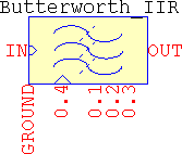
| f0 | Hz | Sampling frequency, set negative for external synchronization, default 5k |
| fp1, fs1, fp2, fs2 | Hz | Corner frequencies for the passband and stopband, defaults <500,400,2k,2.5k> |
| BWp, BWs, fc | Hz | Alternate frequency settings: passband bandwidth, stopband bandwidth, and center frequency, defaults are calculated based on the corner frequencies and, based on those, <1.5k,2.1k,1k> |
| As | dB | Stopband attenuation, absolute values only, default 40 |
| Asc | dB | Frequency-scaling attenuation, absolute values only. If Asc=0, N>0 the passband is optimized. Default 3.0103 |
| N=<0:32> | - | Order of the filter. It represents the order of the lowpass prototype. For bandpass and bandstop, if N=5, it will actually be a 10th order. If N=0, Asc>0, As>0, it determines the minimum order to meet specifications. Default 13 |
| G | - | Gain, linear, default 1 |
| SH=<0,1> | - | Affects the internal sample&hold:
.AC analysis.
|
| sim | s | Total .TRAN simulation time, default 1 |
| tr | s | Rising edge for the internal clock, needs SH=1, default 1m/f0 |
| td | s | Internal clock delay, default 0 |
Chebyshev_IIR
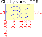
| f0 | Hz | Sampling frequency, set negative for external synchronization, default 5k |
| fp1, fs1, fp2, fs2 | Hz | Corner frequencies for the passband and stopband, defaults <500,400,2k,2.5k> |
| BWp, BWs, fc | Hz | Alternate frequency settings: passband bandwidth, stopband bandwidth, and center frequency, defaults are calculated based on the corner frequencies and, based on those, <1.5k,2.1k,1k> |
| Ap | dB | Passband ripple, absolute values only. If Ap=0, N>0 the passband is optimized. Default 1 |
| As | dB | Stopband attenuation, absolute values only, default 40 |
| Asc | dB | Frequency-scaling attenuation, absolute values only. If Asc≤Ap, Ap is considered. Default 3.0103 |
| N=<0:32> | - | Order of the filter. It represents the order of the lowpass prototype. For bandpass and bandstop, if N=5, it will actually be a 10th order. If N=0, Asc>0, Ap>0, As>0, it determines the minimum order to meet specifications. Default 13 |
| G | - | Gain, linear, default 1 |
| SH=<0,1> | - | Affects the internal sample&hold:
.AC analysis.
|
| nT=<-1,0> | - | Tweak to mimic the response of a passive filter. Even order filters will have the gain at the corner frequencies:
|
| sim | s | Total .TRAN simulation time, default 1 |
| tr | s | Rising edge for the internal clock, needs SH=1, default 1m/f0 |
| td | s | Internal clock delay, default 0 |
InvChebyshev_IIR
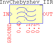
| f0 | Hz | Sampling frequency, set negative for external synchronization, default 5k |
| fp1, fs1, fp2, fs2 | Hz | Corner frequencies for the passband and stopband, defaults <500,400,2k,2.5k> |
| BWp, BWs, fc | Hz | Alternate frequency settings: passband bandwidth, stopband bandwidth, and center frequency, defaults are calculated based on the corner frequencies and, based on those, <1.5k,2.1k,1k> |
| As | dB | Stopband attenuation, absolute values only. If As=0, Asc>0, N>0 the transition band is optimized. Default 40 |
| Asc | dB | Frequency-scaling attenuation, absolute values only. If Asc=0, As>0, N>0 the passband is optimized. If Asc≥As, As is considered. Default 3.0103 |
| N=<0:32> | - | Order of the filter. It represents the order of the lowpass prototype. For bandpass and bandstop, if N=5, it will actually be a 10th order. If N=0, Asc>0, As>0, it determines the minimum order to meet specifications. Default 13 |
| G | - | Gain, linear, default 1 |
| SH=<0,1> | - | Affects the internal sample&hold:
.AC analysis.
|
| sim | s | Total .TRAN simulation time, default 1 |
| tr | s | Rising edge for the internal clock, needs SH=1, default 1m/f0 |
| td | s | Internal clock delay, default 0 |
Cauer_IIR
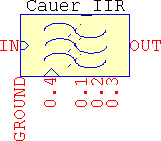
| f0 | Hz | Sampling frequency, set negative for external synchronization, default 5k |
| fp1, fs1, fp2, fs2 | Hz | Corner frequencies for the passband and stopband, defaults <500,400,2k,2.5k> |
| BWp, BWs, fc | Hz | Alternate frequency settings: passband bandwidth, stopband bandwidth, and center frequency, defaults are calculated based on the corner frequencies and, based on those, <1.5k,2.1k,1k> |
| Ap | dB | Passband ripple, absolute values only. If Ap=0, As>0, Asc>0, N>0 the passband is optimized. If Asc≥As, As is considered. Default 3.0103 |
| As | dB | Stopband attenuation, absolute values only. If As=0, Asc>0, N>0 the transition band is optimized. Default 40 |
| Asc | dB | Frequency-scaling attenuation, absolute values only. If Asc≥As, As is considered. If Asc≤Ap, Ap is considered. Default 3.0103 |
| N=<0:32> | - | Order of the filter. It represents the order of the lowpass prototype. For bandpass and bandstop, if N=5, it will actually be a 10th order. If N=0, Asc>0, Ap>0, As>0, it determines the minimum order to meet specifications and optimizes the transition band. Default 13 |
| G | - | Gain, linear, default 1 |
| nT=<-1,0> | - | Tweak to mimic the response of a passive filter. Even order filters will have the gain at the corner frequencies:
|
| SH=<0,1> | - | Affects the internal sample&hold:
.AC analysis.
|
| sim | s | Total .TRAN simulation time, default 1 |
| tr | s | Rising edge for the internal clock, needs SH=1, default 1m/f0 |
| td | s | Internal clock delay, default 0 |
Examples
- Internal sampling on/off. Chebyshev type I bandstop, normalized unity gain, minimum order for a 0.1dB ripple, -0.1dB@[128, 320]Hz, -50dB@[160, 256]Hz, 1024Hz sampling frequecy. Input is a non-sampled
SINE(0 1 300) ac 1source. See the ouput for SH=<0,1> (set to zero to be able to view the.ACresponse):- Chebyshev_IIR
- sigma nT=0 Zin Zout
- Win Choice sim SH=<0,1> Norm
- f0=1024 fp1=128 fs1=160 fp2=320 fs2=256
- G=1 Asc=0 Ap=0.1 As=50 N=0
- External sync. Butterworth highpass, unity gain, -3.0103dB@3kHz, and -60dB@2kHz, 8192Hz sampling:
- Butterworth_IIR
- sigma nT Zin Zout
- Win Choice sim SH=1 Norm
- f0=-8192 fp1=3k fs1=2k fp2=0 fs2=0
- G=1 Asc=3.0103 Ap As=60 N=0
Can be used with external circuit made of SampledSource:XU1 in 0 NC_01 clk SampledSource f0=8192 Freq=3k
where V(in) is the input to the filter and V(clk) is connected to pin 0.4 of Filter. Or use aSINEsource, as mentioned at point 2.b, and see how that influences the transitions. - The test pins: a 5th order Cauer with default frequencies and attenuations (bandpass). The only values that are changed are N, test, sim:
- Cauer
- sigma nT=0 Zin Zout
- Win Choice sim=80m SH=1 Norm
- f0=5k fp1=500 fs1=400 fp2=2k fs2=2.5k
- G=1 Asc=3.0103 Ap=1 As=40 N=5
Finite impulse response
They are built with the same goals in mind as the IIRs (built-in clock, external sync), but they are separated into several versions, each with their own baggage: FIR holds the majority of the windows and functions and allows a maximum 256th order, FIRx is an extended version of FIR that allows a maximum 1024th order, FIR2 has only the computational-heavy Dolph-Chebyshev window and many of FIR's functions, and a maximum 256th order, while FIR_FS implements the frequency-sampling method with the same maximum order of 256 and all the windows from FIR.
All of them make use of all of the available pins, with minor functional differences. Below is shown the pinout for all four FIRs:
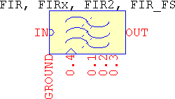
The functions that the FIRs perform are: basic moving average, windowed FIR, pulse shaping, differentiator, and Hilbert transformer, and all of them can be lowpass, highpass, bandpass, and bandstop, while FIR_FS is atypical since it allows for any frequency-domain magnitude specifications. The same .TRAN guidelines as for the IIRs apply here, as well.
The internal configuration is not restricted to symmetrical impulse responses, only, but in order to have anything else besides the already listed options, filter.sub needs to be edited by hand. One way to do it is to comment out the original impulse response function and add a custom one, for example:
.func hn(x) {table(x, ...)} ; where x=[0:N-1]
For the pulse-shaping filters, the setting of oversampling (OS), rolloff (β), and number of symbols (SPS) can be done in two ways (shown in the examples):
-
The most visible way, but clumsy, is by using:
- SPS = nT (think Number of symbols per period, T)
- OS = nT*f0/(fp1 + fs1) = nT*f0/(BWp + BWs)
- β = (fs1 - fp1)/(fs1 + fp1) = (BWs - BWp)/(BWs + BWp)
- N = OS*SPS
- The hidden way: directly set nT (SPS), OS (OS), and beta (β), the last two parameters being hidden and used, internally, to calculate the above settings. When these parameters are set manually, the equations from the previous point will be ignored.
FIR
-
Pin 0.1 outputs the order: in
.TRANit's in V, and in.ACit's in dB and deg. Zero resistance output. - Pin 0.2 outputs the weights and pin 0.3 outputs the impulse response, but only in the time domain. For best readings, sim should be set to match the total simulation time.
- For all, pin 0.4 allows external synchronization, and has 1GΩ internal resistance.
| Win=<0:29> | - | Selects the window:
|
| Func=<0:6> | - | Selects between the available functions:
|
| f0 | Hz | Sampling frequency, set negative for external synchronization, default 5k |
| fp1, fs1, fp2, fs2 | Hz | Corner frequencies for the passband and stopband, defaults <500,400,2k,2.5k> |
| BWp, BWs, fc | Hz | Alternate frequency settings: passband bandwidth, stopband bandwidth, and center frequency, defaults are calculated based on the corner frequencies and, based on those, <1.5k,2.1k,1.3k> |
| As | dB | Stopband attenuation, absolute values only. Only used by these windows:
|
| N=<0:257> | - | Length of the filter. If N=0 the minimum order is determined based on:
|
| G | - | Gain, linear, default 1 |
| sigma | - | Factor for the parametric windows:
|
| Norm=<0,1> | - | Enables or disables the gain normalization. This only applies for :
|
| SH=<0,1> | - | Affects the internal sample&hold:
.AC analysis.
|
| nT=<0,1:∞> | - | Has two roles:
|
| sim | s | Total .TRAN simulation time, default 1 |
| a0, a1, a2, a3, a4 | - | Terms for the generic cosine window, default <0.2, 0.4, 0.3, 53m, -3m> |
| tr | s | Rising edge for the internal clock, needs SH=1, default 1m/abs(f0) |
| td | s | Internal clock delay, default 0 |
FIRx
ltline with lininterp instead of tline, and N=<0:1025>.
FIR2
- This one has only the Dolph-Chebyshev window, which is computationally-heavy. All the other functions from FIR are here, too, except the gaussian pulse-shaping – which is not used windowed, so it doesn't make much sense to add this to a slower version of a FIR. Using Func=2 will result in the output being the window itself.
- Due to the heavy formulas, the sum of terms slows down everything triple-fold, or worse, so there is no gain normalizing, except for the differentiator.
- The automatic determination of order is done via the formula from Saramäki.
- In short, it's the same as FIR except it doesn't have Win, Norm, and the hidden a[0:4], and has the same max order of 256.
FIR_FS
- Similar to FIR except it implements the frequency sampling method, which is the only function that it performs (there is no Func parameter). It has all the windows, except the Dolph-Chebyshev and the spline transition.
-
Using it requires entering the frequency response, which can only be done as a function. Since LTspice doesn't allow time-based parameters to be passed to a subcircuit (it needs to calculate them prior to simulation), using it means editing in the subcircuit file the function:
.func fspl(x) {...} ; x=[0..(N-3)/2+nT]
defined from 0 until Nyquist. There are a few examples in the subcircuit. -
Pin 0.1 outputs the type (from I to IV): in
.TRANit's in V, and in.ACit's in dB and deg. Zero resistance output. - In the time domain, pin 0.2 outputs the user frequency-domain function, and pin 0.3 outputs the impulse response. For best readings, sim should be set to match the total simulation time.
- For all, pin 0.4 allows external synchronization, and has 1GΩ internal resistance.
| Win=<0:29> | - | Selects the window:
|
| f0 | Hz | Sampling frequency, set negative for external synchronization, default 5k |
| As | dB | Stopband attenuation, absolute values only. Only used by these windows:
|
| N=<1:257> | - | Length of the filter, default 33 |
| G | - | Gain, linear, default 1 |
| sigma | - | Factor for the parametric windows:
|
| SH=<0,1> | - | Affects the internal sample&hold:
.AC analysis.
|
| nT=<0,1> | - | Sets the sampling method:
|
| sim | s | Total .TRAN simulation time, default 1 |
| a0, a1, a2, a3, a4 | - | Terms for the generic cosine window, default <0.2, 0.4, 0.3, 53m, -3m> |
| tr | s | Rising edge for the internal clock, needs SH=1, default 1m/abs(f0) |
| td | s | Internal clock delay, default 0 |
Examples
- Func=0
- Basic moving average
- Func=1
- Lowpass
- Highpass
- Bandpass
- Bandstop
- Func=<2,3,4>
- Gaussian pulse-shaping
- Raised cosine
- (Square-)root raised cosine
- Func=<5,6>
- Differentiator
- Hilbert transformer
- Frequency sampling
- Interpolated FIR
- The test pins
Func=0
- Basic moving average: 20 points average, 1kHz sampling frequency, non-windowed:
- FIR
- sigma nT Zin Zout
- Win=0 Func=0 sim SH=<0,1> Norm
- f0=1k fp1 fs1 fp2 fs2
- G=1 Asc Ap As N=20
Apply different windows through Win=<1:29>, in which case sigma, nT, and As might also need changed, depending on the window.
Func=1
- Lowpass: Hann, length 11, 2kHz sampling frequency, ωc=370Hz, unnormalized unity gain:
- FIR
- sigma nT Zin Zout
- Win=16 Func=1 sim SH=<0,1> Norm=0
- f0=2k fp1=340 fs1=400 fp2=0 fs2=0
- G=1 Asc Ap As N=11
- Highpass: Dolph-Chebyshev, minimum order for a -60dB@224Hz, 0dB@256Hz, 1024Hz sampling frequency, normalized unity gain, non-null end taps:
- FIR2
- sigma nT Zin Zout
- Win Func=1 sim SH=<0,1> Norm
- f0=1024 fp1=250 fs1=200 fp2=0 fs2=0
- G=1 Asc Ap As=60 N=0
The resulting filter is a type II highpass and, while technically possible, that is not here, and not found in real life applications, so the order needs to be increased by one in order to see the highpass. The attenuation is too large, and by reducing it, the order also needs to be increased. This is a recursion that cannot be done in LTspice, so it falls to the user.
- Bandpass: Kaiser, minimum order for a 0dB@[6kHz, 8kHz], -60dB@[6.2kHz, 7.8kHz] 8192Hz sampling frequency, unity gain. It's a brick wall filter, large attenuation, so the resulting order will be probably mean FIRx is needed:
- FIRx
- sigma nT Zin Zout
- Win=19 Func=1 sim SH=<0,1> Norm=1
- f0=44.1k fp1=6k fs1=6.2k fp2=8k fs2=7.8k
- G=1 Asc Ap As=60 N=0
- Bandstop. A test for the generic cosine window (simply add the missing terms):
- FIR
- sigma nT Zin Zout a0=0.3 a1=0.5 a2=0.19 a3=9m a4=1m
- Win=14 Func=1 sim SH=<0,1> Norm=1
- f0=2 fp1=0.4 fs1=0.5 fp2=0 fs2=0
- G=1 Asc Ap As N=33
Func=<2,3,4>
- Gaussian pulse-shaping. Use the visible, but clumsy method:
N = OSR*nsym + 1 = 4*12 + 1 = 49
fp1 = f0*nsym*(1 - β)/(2*OSR) = 3.84MHz*12*(1 - 0.22)/(2*4) = 4.4928MHz
fs1 = f0*nsym*(1 + β)/(2*OSR) = 3.84MHz*12*(1 - 0.22)/(2*4) = 7.0272MHzSince the order is imposed, nT may be omitted.
- FIR
- sigma nT Zin Zout
- Win=0 Func=2 sim SH=<0,1> Norm=0
- f0=3.84meg fp1=4.4928meg fs1=7.0272meg fp2=0 fs2=0
- G=1 Asc Ap As N=49
- Raised cosine. Use the direct, hidden method, by using nT = nsym, and simply adding the two parameters:
- FIR
- sigma nT=12 Zin Zout OS=4 beta=0.22
- Win=0 Func=3 sim SH=<0,1> Norm=0
- f0=3.84meg fp1 fs1 fp2 fs2
- G=1 Asc Ap As N
- (Square-)root raised cosine, same as its cousin above, but with Func=4.
Func=<5,6>
- Differentiator: unity gain at 0.1Hz, slope until 0.3Hz, -80dB@0.4Hz, 1Hz sampling frequency, minimum order to meet the specifications, exponential window. The normalizing for the differentiator is done at fp1. Since the corner frequency extends beyond the frequency where the unity gain is needed, normalize the gain with Norm=1 and use a gain equal to the ratio of the slopes: fp1/funity = 0.3/0.1 = 3.
- FIR
- sigma nT Zin Zout
- Win=11 Func=5 sim SH=<0,1> Norm=1
- f0=1 fp1=0.3 fs1=0.4 fp2 fs2
- G=3 Asc Ap As=80 N=0
- Hilbert transformer: a 1024th order spline transition window.
- FIRx
- sigma=1 nT Zin Zout
- Win=26 Func=6 sim SH=<0,1> Norm=1
- f0=10k fp1=1k fs1=1.1k fp2 fs2
- G=1 Asc Ap As N=1025
Interpolated FIR
If a single FIR is used, the resulting order is 502. Using a two-stage IFIR, the resulting orders will be:
- 2x ⇒ 251 downsampler and 18 upsampler
- 3x ⇒ 168 downsampler and 41 upsampler
- 4x ⇒ 126 downsampler and 126 upsampler
- IFIR:
- FIR (downsampler)
- sigma nT Zin Zout
- Win=19 Func=1 sim SH=<0,1> Norm=1
- f0={-2/Rate} fp1=0.2 fs1=0.22 fp2=0 fs2=0
- G=1 Asc Ap As=80 N=0
- FIR (upsampler)
- sigma nT Zin Zout
- Win=19 Func=1 sim SH=<0,1> Norm=1
- f0={-2} fp1=0.2 fs1={2/Rate-0.22} fp2=0 fs2=0
- G={Rate} Asc Ap As=80 N=0
- Normal FIR:
- FIRx
- sigma nT Zin Zout
- Win=19 Func=1 sim SH=<0,1> Norm=1
- f0=-2 fp1=0.2 fs1=0.22 fp2=0 fs2=0
- G=1 Asc Ap As=80 N=0
Frequency sampling
- FIR_FS
- sigma nT=<0,1> Zin Zout
- Win=15 Func=1 sim SH=<0,1> Norm=1
- f0=10k fp1 fs1 fp2 fs2
- G=1 Asc Ap As N=<64,65>
The test pins
.TRAN card, the values will fill the entire timespan. The only differences between the frequency sampling and the rest of the FIRs is that the first will output the FIR type, the frequency-domain formula, and the impulse response, and the others will output the order, the weights, and the impulse response.
Moving average filters
MAFv
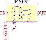
- Its implemented with an integrator and a behavioural source with delay(), so expect drifts and minor inconsistencies, influenced by the timestep and/or the complexity of the circuit.
- Pin 0.4 is used to provide external time window (period) for the integration. Anything connected to this pin overrides internal settings. Rin=1GΩ.
| f0 | Hz | Inverse of the period of the sliding window, default 1k |
| G | - | Gain, linear, default 1 |
| Rpar | Ω | LTspice's specific for capacitors, default 1g |
| lim | V | Internal limits to avoid clipping, default 1g |
RRS
-
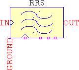
It's implemented with delay lines, no sampling, and for signals that don't start at zero, the filter may not give the correct response, so forcing initial conditions at the input may be needed:
.ic V(in)=0
When initial conditions fail,
uicis the only solution left (besides modifying the circuit to force a zero input prior to filtering). - The averaging period is set by f0*N.
| f0 | Hz | Inverse of the period of the discrete integrator, default 1k |
| G | - | Gain, linear, default 1 |
| N | - | Number of samples per period, default 10 |
Examples
- Variable moving average. Filtering a variable input signal means anything connected to pin 0.4 will override the settings for f0 (it doesn't matter what value is assigned to):
- MAFv
- sigma nT Zin Zout
- Win Func sim SH Norm
- f0=x fp1 fs1 fp2 fs2
- G=1 Asc Ap As N
- Running recursive sum with a cosine input plus offset (
SIN(1 1 1k 0 0 90)) and 10 samples long period. As it is, the filter will obviously give the wrong output, but forcing initial conditions to be zero for the filter's input don't work for this simple case, so adduicto the simulation card:- RRS
- sigma nT Zin Zout
- Win Func sim SH Norm
- f0={10*1k} fp1 fs1 fp2 fs2
- G=1 Asc Ap As N=10
Custom filters
3dBoct
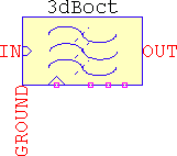
| fp1 | Hz | Corner frequency, default 100 |
| BWp | Hz | Alternate frequency settings: passband bandwidth, default fp1 |
| N=<0:1:32> | - | Number of series RC cells, default 32 |
| sigma | - | Makes the response around the corner frequency smoother or sharper, default 1 |
| nT | - | Sets the distance between the RC cells along the spectrum, and it's the base for the power of two, (2+nT)n, default 0 |
| Rpar | Ω | LTspice's specific for capacitors, default 1G |
Examples
- This example emulates a cheap audio pink noise filter for the range of <20Hz..20kHz>, with 5 RC cells spaced every 3x frequency. Since the filter is configured to work as a lowpass, the corner frequency should be set a decade earlier and the gain 10x the desired one. For this case, f=20Hz/10=2Hz and G=1*10=10. The default spacing is octave-based, so to make it 3x set nT=1 to have (2+nT)n=3n. Adjust sigma and fp1 (or BWp) to fit the needs. Set the analysis to
.ac dec 100 2 2megto view the response.- 3dBoct
- sigma=1 nT=1 Zin Zout
- Win Func sim SH Norm
- f0 fp1=2 fs1 fp2 fs2
- G=10 Asc Ap As N=5
Due to the influence of sigma and nT, the corner frequency is shifted, so to correct it set fp1=1. For a better fidelity, set a higher N and lower (minimum -1) nT.